
Scanning for a 3D-printed surgical case
The accuracy of a surgical guide, model or implant is limited by the scan it is built from, not by the printer.
Check a scan before sending itWhat makes a scan usable
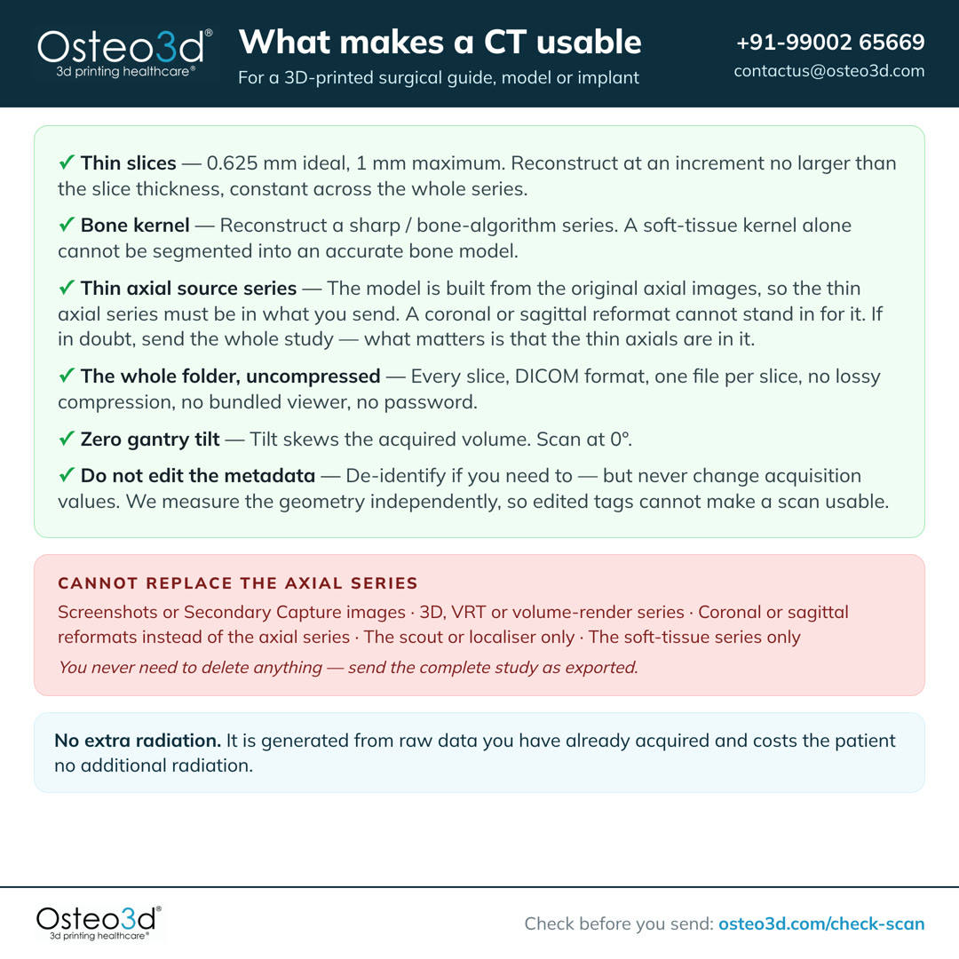
Thin slices
Under 1 mm. 0.625 mm is best. Set the reconstruction increment (interval) no larger than the slice thickness.
Bone kernel
Reconstruct a sharp bone-algorithm series. Send the soft-tissue series too.
Thin axial source series
Send the thin axial series. A reformat cannot replace it.
The whole folder, uncompressed
Send the study as exported — every slice, one DICOM file each. No compression, no password.
Zero gantry tilt
Scan at 0°. No tilt, no oblique acquisition.
Do not edit the metadata
De-identify if you must. Never change acquisition values.
A thin bone-kernel series is a reconstruction, not a second scan. It is generated from raw data you have already acquired and costs the patient no additional radiation.
Check one slice before the patient leaves
Drop a single image from the thin series into the checker. Slice thickness, kernel, gantry tilt, matrix and compression are all readable from one file. A wrong setting found now needs only a new reconstruction. After the patient has left it needs a repeat scan.
One slice cannot show missing slices, the true slice spacing, or whether every slice agrees with the others. Send the full study for that.
Check a sliceTick them off at the scannerOpenClose
CT · All Cases
Universal Imaging Requirements
Under 1 mm, ideally 0.625 mm. Reconstruct a bone series and a soft-tissue series at this thickness.
The reconstruction increment, also called the interval, must be no larger than the slice thickness. It must stay the same across the whole series.
Send the original axial series. A thin axial volume reformats into coronal and sagittal views automatically, so separately reconstructed reformats are not needed and cannot be used in their place.
Reconstruct with a bone / sharp kernel and also send the soft-tissue series. Both are used in planning.
Share the complete unprocessed, uncompressed DICOM folder exactly as exported — every slice, one file per slice, no lossy export.
The patient must remain completely still throughout. A scan with motion artifacts cannot be used and will require a repeat.
Export at native resolution — no downsampling. If the export dialog offers X, Y and Z ratios, set all three to 1:1.
Scan at 0° tilt with no oblique acquisition. A tilted acquisition produces a skewed volume in which anatomy is displaced progressively along the scan.
Remove jewellery, braces and metallic items. Where hardware or restorations cannot be removed, apply the scanner's MAR algorithm (iMAR / O-MAR / SEMAR / CLIMAR) and send BOTH the original and MAR-corrected series.
Recommended Convolution Kernel by Scanner Brand
| Scanner | Kernel / Algorithm |
|---|---|
| GE | Bone, Boneplus, HDBONE, Ultra |
| Philips | D, E, YA, YB, YC, YD |
| Siemens | B60, B70, B75, B80 (legacy); Br56, Br59, Br69 (ADMIRE) |
| Toshiba / Canon | FC30, FC50, FC80, FC81 |
| UIH | Sharp |
Procedure-Specific Checklist
Head & Neck · Orthognathic · Zygoma
- CT of head and neck
- Jaw open 1 cm — non-radio-opaque prop only (foam / cotton) — NOT metal
- Intraoral scan: upper arch, lower arch, bite registration — .stl / .obj / .plyRequiredIf intraoral scan not feasible: courier stone models
- Clinical photos: full face (anterior), lateral view, upper arch, lower arch, bite
Service limited to bony movement simulations — does not extend to soft tissue prediction.
Zygoma — Option A
- CT or optical scan of the temporary prosthesis / denture
- CT of head and neck — jaw open 1 cm, non-radio-opaque prop
- CT of head and neck — prosthesis in occlusion (biting down)
Zygoma — Option B
- CT of temporary prosthesis with radio-opaque markers
- CT of head and neck — marked prosthesis in occlusion
Send this to whoever is scanning
The same six rules, on one page and in one film.
Or the card for your scanner
One manufacturer, one kernel, and the export trap on that system.
Narrated, with every word also on screen, so it works with the sound off.
These six apply to every CT. MRI has its own requirements. Each procedure adds to them.
Protocol in detail
Console settings, export, CBCT, MRI, fusion, and what each procedure needs.
At the console
Slice thickness, increment, kernel, matrix, field of view and tilt — and the bone kernel for your scanner make.
These are the console settings for a CT that will be used to build a patient-specific model, guide or implant. Where a value is not listed, use your standard diagnostic protocol.
Applies to every case, whatever the procedure
- 1
Slice Thickness. Under 1 mm, ideally 0.625 mm. Reconstruct a bone series and a soft-tissue series at this thickness.
- 2
Reconstruction Increment. The reconstruction increment, also called the interval, must be no larger than the slice thickness. It must stay the same across the whole series.
- 3
Axial Source Images. Send the original axial series. A thin axial volume reformats into coronal and sagittal views automatically, so separately reconstructed reformats are not needed and cannot be used in their place.
- 4
Bone and Soft Tissue. Reconstruct with a bone / sharp kernel and also send the soft-tissue series. Both are used in planning.
- 5
RAW DICOM Folder. Share the complete unprocessed, uncompressed DICOM folder exactly as exported — every slice, one file per slice, no lossy export.
- 6
Zero Motion. The patient must remain completely still throughout. A scan with motion artifacts cannot be used and will require a repeat.
- 7
Export at 1:1. Export at native resolution — no downsampling. If the export dialog offers X, Y and Z ratios, set all three to 1:1.
- 8
Zero Gantry Tilt. Scan at 0° tilt with no oblique acquisition. A tilted acquisition produces a skewed volume in which anatomy is displaced progressively along the scan.
- 9
Metal / Artefact. Remove jewellery, braces and metallic items. Where hardware or restorations cannot be removed, apply the scanner's MAR algorithm (iMAR / O-MAR / SEMAR / CLIMAR) and send BOTH the original and MAR-corrected series.
Console settings
| Parameter | Setting | Notes |
|---|---|---|
| Slice thickness | 0.625 mm ideal · 1.0 mm maximum | Above 1.5 mm a scan cannot be used for surgical guides or implants. |
| Reconstruction increment (interval) | ≤ slice thickness, contiguous | Overlap improves the result. A larger increment leaves anatomy unsampled. |
| Consistency | Constant throughout the acquisition | No change in thickness, increment, FOV or centring mid-series. |
| Reconstruction kernel | Bone / sharp | Plus a soft-tissue series. See the kernel table below for your scanner. |
| In-plane pixel size | Under 1.0 × 1.0 mm | Typically 0.3–0.5 mm at a 250 mm display FOV. |
| Matrix | 512 × 512 | Square matrix. Some scanners default to rectangular — set it manually. |
| Display FOV | Smallest that encloses the full anatomy | 250–320 mm for head and neck. Do not clip the region of interest. |
| kVp | 120 (140 for large patients) | Use a lower kV only when boosting iodine contrast for a vascular model. |
| mA | Auto / tube current modulation | Apply your standard dose-optimisation and paediatric protocols. |
| Pitch | ≤ 1 (helical) | GE: High Quality. Canon / Toshiba: Detail. |
| Rotation time | 1 second or less | |
| Gantry tilt | 0° | No tilt, no oblique acquisition. |
| Table | Do not change height or X/Y centring mid-scan | Changing it means the slices no longer form a single volume. |
| Series | All images in one series | Do not split the acquisition across several series. |
| Compression | Uncompressed or lossless only | Lossy compression permanently destroys the data we segment. |
Recommended convolution kernel by scanner
| Scanner | Kernel / algorithm |
|---|---|
| GE | Bone, Boneplus, HDBONE, Ultra |
| Philips | D, E, YA, YB, YC, YD |
| Siemens | B60, B70, B75, B80 (legacy); Br56, Br59, Br69 (ADMIRE) |
| Toshiba / Canon | FC30, FC50, FC80, FC81 |
| UIH | Sharp |
If your scanner is not listed, choose the sharpest bone or high-resolution algorithm available and send the soft-tissue series alongside it. Tell us which kernel you used and we will confirm it.
You may have seen protocols from implant companies that ask for a smooth or standard kernel rather than a bone kernel. Both are correct for their purpose: a smoothing kernel suits guides that seat on a broad, smooth cortical surface, where edge-enhancement noise disturbs the fit. Craniomaxillofacial and fine-bone work needs the detail a sharp kernel preserves. For our cases, reconstruct bone — and send the soft-tissue series too.
Label the series
Where your scanner allows it, set the Study Description to this string on the thin bone series. It makes the correct series easy to find in PACS later, including by someone who was not present at the scan.
O3D THIN AXIAL BONEKeep the raw data
Please retain the raw scan data for at least 14 days. If anything is wrong with the export, a retained raw dataset lets us fix it by re-reconstructing — with no repeat scan and no additional dose to the patient.
Exporting the study
Where most unusable data is created. The export rules, the trap on each vendor’s workstation, and what cannot be used.
This is where most unusable data is created. The scan itself is often correct; what reaches us is a reformat, a screenshot, or a compressed copy. These rules hold on every scanner and workstation, whatever the menu is called.
- Export from the source series — never from a 3D, MPR or reformat view.
- Format: DICOM, one file per slice ("multi-file", or "set of single frame DICOM files"). Not JPEG, BMP, PDF, video, or "save image".
- Compression: uncompressed, none, or lossless. If asked for a ratio, choose 1:1 on X, Y and Z.
- Range: every slice in the series. Do not sub-sample and do not crop the range.
- Do not bundle a viewer application, and do not password-protect or encrypt the archive.
- Zip the folder and upload the zip, or upload the folder directly.
- Include the thin bone-kernel axial series. Include the soft-tissue series alongside it.
Known traps on specific systems
GE (console / AW workstation)
On the AW workstation, "Save Image" produces a Secondary Capture — effectively a screenshot in a DICOM wrapper, with no usable geometry. Use Save As / Export → DICOM instead, and export the source series rather than a Volume Viewer result.
Siemens (syngo / syngo.via)
Add the thin bone reconstruction as a separate recon job at the console; it is not created automatically. Some models — the SOMATOM GO in particular — default to a non-square matrix and must be set manually to 512 × 512. Export via Patient Browser → Export → DICOM, offline / uncompressed, and do not attach the syngo viewer.
Philips (console / IntelliSpace)
Export via IntelliSpace → Export → DICOM, uncompressed. Send the source axial series, not an IntelliSpace 3D or MPR result series.
Canon / Toshiba (Aquilion)
Select an FC-series bone kernel (FC30, FC50, FC80, FC81) and export the reconstructed volume, not a screen result. Use the Detail pitch mode.
CBCT (Planmeca, Carestream, Sirona, NewTom, Vatech, i-CAT)
Export as multi-file DICOM with a .dcm extension — in Planmeca Romexis this is Output → Export Volume → "Set of Single Frame DICOM Files", exported to a folder. Set X, Y and Z to 1:1; leaving them at 2:1 or 4:1 silently halves your resolution. A correct export is typically 100 or more .dcm files. Do not send a proprietary volume file (.vol, i-Dixel) or a disc containing only the viewer.
What we cannot use
Each of these arrives regularly, and none can be used in place of the axial series. Nothing needs to be deleted — send the complete study as exported. If what you have is on this list, the original data is almost always still on the scanner.
| Screenshots or Secondary Capture images | A picture of the study, not the study. It carries no slice geometry. | |
| 3D, VRT or volume-render series | Already segmented by the workstation, at settings we cannot verify or reverse. | |
| Coronal or sagittal reformats instead of the axial series | A reformat is a resampling of the axials and carries no geometry they do not already have. Send the axial series; extra reformats alongside it are fine. | |
| The scout or localiser only | A positioning image, not a diagnostic volume. | |
| The soft-tissue series only | Bone edges are blurred by the smoothing kernel and cannot be thresholded accurately. | |
| The thick reporting series only | The 3–5 mm series goes to PACS; the thin series usually exists on the scanner and is what we need. | |
| A report PDF, JPEG images, or an AVI cine | Not imaging data. | |
| Lossy / JPEG-compressed DICOM | Detail is permanently discarded. The file records this, so it cannot be recovered. | |
| A series with missing slices, or an increment larger than the slice thickness | The model will have holes or wrong dimensions along the scan axis. | |
| A tilted or oblique acquisition | The volume is skewed; anatomy is displaced increasingly along the scan. | |
| One study split across several series | The slices no longer form a single continuous volume. | |
| A scan that clips the region of interest | Anatomy outside the field of view cannot be reconstructed. | |
| Images with burned-in annotation over anatomy | The text is part of the pixel data and corrupts segmentation. | |
| A disc containing only a proprietary viewer | We need the DICOM files themselves, not the viewer application. | |
| A password-protected or encrypted archive | It cannot be opened by our intake system. |
Why these numbers
The reasoning behind each requirement, and the RSNA 3D printing guidance it follows.
Each requirement follows from how a 3D model is built out of a stack of images.
Why slice thickness is the parameter that matters most
A structure is only reconstructed accurately if it appears on several consecutive slices. The RSNA 3D Printing Special Interest Group states it directly: for anatomy measuring 3 mm, that anatomy should be captured on at least 3 sequential images, so slice thickness should be no greater than 1 mm and preferably smaller. Below that threshold the surface is interpolated rather than measured, and the model shows visible stair-stepping along the scan axis.
Why the increment must be no larger than the thickness
Slice thickness is how thick each reconstructed slice is. The increment is how far the slice positions step. Set them equal and the slices sit edge to edge, with nothing between them left unimaged. Set the increment larger than the thickness and there is anatomy nobody scanned, which the reconstruction has to invent. Set it smaller and the slices overlap, which measurably improves the result.
Why a bone kernel, and why we still want the soft-tissue series
Sharp kernels preserve edge definition at the cost of noise; smoothing kernels reduce noise at the cost of edge definition. Bone segmentation depends on a threshold applied at the bone–soft-tissue boundary, so a blurred edge moves that boundary and shifts every dimension of the model. The soft-tissue series remains useful for airway, vessels and the surrounding anatomy.
Why gantry tilt is a hard requirement
Head CT commonly uses 10–15° of tilt to spare the orbits. That produces an acquisition grid where the slice planes and the direction of table travel are not perpendicular. Most reconstruction software assumes they are, and silently stacks the volume as if it were orthogonal — displacing anatomy progressively along the scan, by centimetres at the far end. We detect and correct this, but a scan acquired at 0° needs no correction at all.
Why compression cannot be accepted
Lossy compression discards information judged imperceptible to a human reader. Segmentation is not a human reader: it operates on exact voxel values at a threshold, and the discarded detail sits precisely at the edges that define the model. The loss is recorded in the file and is not reversible.
Why the printer is never the limiting factor
Our printers build in layers of tens of microns. A CT voxel is typically 300–700 microns. The scan is always the constraint on accuracy, which is why protocol matters far more than print technology.
These requirements align with the guidelines published by the Radiological Society of North America 3D Printing Special Interest Group. Where your clinical judgement calls for a different protocol, contact us before the scan and we will work to it.
CBCT
Where cone beam CT can be used, where medical CT is required, and the voxel and export settings.
CBCT is acceptable for some procedures and not for others.
CBCT is acceptable for
- Tooth-borne dental implant guides
- Gross craniomaxillofacial anatomical models
- Orthognathic planning where bone morphology, not density, drives the plan
Medical CT is required for
- Load-bearing titanium patient-specific implants
- Condylar, temporal bone and other fine-detail anatomy
- Any case where tissue density or Hounsfield values inform the design
- Cranial flap moulds and cranial helmets
If you are using CBCT
- Voxel size 0.3–0.4 mm or smaller, isotropic.
- Smallest field of view that fully encloses the anatomy — but it must enclose all of it. Truncated anatomy cannot be reconstructed.
- Immobilise the patient properly. CBCT scan times are long and most units scan seated or standing, which makes motion the most common cause of an unusable CBCT.
- Export as multi-file DICOM at a 1:1 ratio on all three axes (see Exporting the study).
CBCT grey values are not true Hounsfield units, and they shift depending on where the anatomy sits within the field of view. This means a segmentation threshold cannot be carried over from CT or from another CBCT — it has to be set visually for each case, which is why CBCT-derived models carry a quality note.
Radiation-protection guidance correctly tells you to use the largest voxel size consistent with the diagnostic task. A 3D-printed guide is a different task from a diagnostic read, and it needs finer voxels than diagnosis alone would justify. Where the case allows it, reduce the field of view rather than coarsening the voxel.
By procedure
What each procedure needs on top of the general requirements — ten procedure types.
Each procedure has requirements beyond the six above.
Free Flap Fibula Surgery
- CT of head and neck (jaw open with a 1 cm gap using non-radio-opaque aid). If an MRI is also being taken for this case, it must be scanned with the SAME 1 cm gap — the jaw position has to match on both scans or the two cannot be registered.
- MRI, where tumour extent must be located on the bone model: 3D isotropic, 1.0 mm voxel or smaller, distortion correction on, and the same day and jaw position as the CT. A thick or non-isotropic MRI cannot carry a margin onto the model. See Registering MRI to CT for the full protocol.
- CT Angiography of lower limbs — ensure all vessels are clearly visualized.
- Intraoral scans of upper and lower arches and bite scan are recommended — to be shared in .stl or .obj or .ply file format.
- Provide dental drill sleeves for your chosen implant system to enable integration with the fibula guide.
Moulds for Cranioplasty with PMMA Implants
- CT of the entire head and neck region.
Spine and Vertebral Models
- Contrast-enhanced CT required if vertebral artery tracing and visualization is needed.
Orthognathic Surgery
- CT of head and neck (jaw open with a 1 cm gap using non-radio-opaque aid).
- Position the patient so the occlusal plane coincides with the axial slices — check this on the scout and with the scanner's laser pointers.
- Intraoral scans of upper and lower arches and bite scan are mandatory — to be shared in .stl or .obj or .ply file format.
- If intraoral scan is not feasible, courier us the stone models.
- Clinical photographs of the upper and lower arch, bite and full face (anterior, lateral).
Note: This service is limited to bony movement simulations and does not extend to soft tissue prediction.
Dental Implant Planning
- CT of head and neck only (jaw open with a 1 cm gap, use a non-radio-opaque aid if needed).
- Intraoral scans of the upper and lower arches, and bite scan are mandatory — to be shared in .stl or .obj or .ply file format.
- CT or optical scan of the temporary prosthesis/denture.
- CT of head and neck while wearing the temporary prosthesis in occlusion.
- Provide dental drill sleeves for your chosen implant system to enable integration with the guide.
Zygoma Implant Planning
- CT of head and neck (jaw open with a 1 cm gap using non-radio-opaque aid).
- Intraoral scans of upper and lower arches and bite scans are mandatory — to be shared in .stl or .obj or .ply file format.
- If intraoral scan is not feasible, courier us the stone models.
Option A
- CT or optical scan of the temporary prosthesis.
- CT of head and neck (jaw open with a 1 cm gap using non-radio-opaque aid).
- CT of head and neck with temporary prosthesis in occlusion.
Option B
- CT of temporary prosthesis (with radio-opaque markers).
- CT of head and neck with prosthesis (with markers) in occlusion.
Titanium Patient-Specific Implants (Ti-PSI)
- CT of head and neck with a slice thickness of 0.625 mm only.
- It is critical that there are no artifacts of any kind present in the scan.
- Scan must fully capture the region of interest and surrounding anatomy.
- Medical CT only — CBCT cannot be used for load-bearing patient-specific implants.
Orthopedic Models
- Scan must fully capture the region of interest and surrounding anatomy.
- Contrast-enhanced CT / CT Angiography required if arterial tracing and visualization is needed.
Cranial Helmets
- CT scan of the head and neck must be taken with a slice thickness of 1 mm or less.
- Scan must fully capture the area of interest and surrounding anatomy.
- Soft padding may be used to stabilize the head, but it must not distort the natural contour of the head or ears. Avoid any materials or devices (e.g., bandages, catheters, monitoring equipment) that could interfere with or alter head shape.
- If the CT scan is more than 30 days old, or if there are noticeable changes in head shape, alternate imaging or additional measurements may be required.
Anatomical Models and Surgical Guides
- CT of head and neck with a slice thickness of 0.625 mm only.
- Scan must fully capture the region of interest and surrounding anatomy.
- If applicable, CT scan of the entire head and neck (jaw open with a 1 cm gap, use a non-radio-opaque aid if needed).
MRI — soft tissue
Sequence by target tissue, resolution, motion control and export, for soft-tissue models.
CT is ideal for bone; for soft-tissue models — tumours, vasculature, cardiac, organs, and cartilage — we work from MRI. Unlike CT, MRI has no fixed density scale (no Hounsfield units), so two things make an MRI segmentable into an accurate 3D-printable model: the right sequence for the target tissue, and high-resolution, gap-free 3D geometry. Because MRI protocols vary by scanner and vendor, please involve us before the scan so we can help tailor the sequence.
- 1
Acquire a true 3D volumetric sequence (e.g. MPRAGE, SPACE / CUBE / VISTA, VIBE, or bSSFP) — not thick 2D multi-slice stacks.
- 2
Target ≤1 mm isotropic voxels (ideally smaller). Rule of thumb: the smallest structure of interest should appear on at least 3 consecutive slices.
- 3
Slices must be contiguous with no inter-slice gap. Thick or gapped slices produce stair-stepped, inaccurate models.
- 4
Aim for signal-to-noise and contrast in the region of interest at least as high as you would use for 3D visualisation.
- 5
3T is preferred where resolution and SNR matter (brain, prostate, tumour); 1.5T is fully acceptable for cardiac and most musculoskeletal work.
- 6
Control motion: breath-hold or respiratory navigation for abdomen and liver; ECG gating (± respiratory navigation) for cardiac.
- 7
Use fat suppression (Dixon-based) where fat would obscure the target, e.g. abdomen, liver, and post-contrast tumour.
- 8
Acquire true axial or sagittal slices — do not acquire obliquely.
Recommended sequence by target tissue
| Target | Preferred sequence(s) | Notes |
|---|---|---|
| Tumour / oncology (brain, liver, renal) | Post-contrast 3D T1 (SPACE / CUBE / VISTA); VIBE alternative; MPRAGE for grey/white-matter contrast | Gadolinium-enhanced, ~1 mm isotropic. 3T; Dixon fat-saturation for body regions. |
| Cardiac / congenital heart | 3D bSSFP / SSFP (TrueFISP / FIESTA) plus contrast-enhanced 3D FLASH angiography | ECG-gated ± respiratory navigation. 1.5T common. ~1 mm isotropic. |
| Vascular / aneurysm | Contrast-enhanced MRA (3D T1 spoiled GRE); TOF or SSFP alternative for lumen | Radiation-free alternative to CT angiography. Contact us to confirm the protocol. |
| Neuro / musculoskeletal / fetal | Brain: 3D T1 MPRAGE + 3D T2 / FLAIR. Cartilage / labrum: MP2RAGE or 3D T2 TrueFISP. Fetal: fast single-shot | Brain and MSK at 3T (MSK also 1.5T), ~1 mm isotropic. Fetal uses motion-freezing sequences. |
DICOM export
- Share the complete RAW, uncompressed DICOM of the single 3D series — no lossy JPEG, no screenshots or reformatted secondary captures.
- Preserve slice geometry (Image Position / Orientation Patient) so the volume reconstructs accurately.
- One contiguous series per model, correctly labelled, so we can identify the 3D volume rather than a localiser or derived map.
Note: MRI segmentation is more involved than CT, and protocols vary by scanner and vendor. These recommendations align with the RSNA 3D Printing Special Interest Group guidelines — please contact us before scanning so we can confirm the exact sequence for your case.
MRI + CT fusion
Acquiring the CT and the MRI so they can be registered to each other. Read this before booking either scan.
Some cases need the MRI and the CT registered to each other, so that soft-tissue extent seen on MRI can be located on the bone model built from CT. This is a different requirement from MRI on its own, and it constrains how both scans are acquired. Please read this section before booking either scan.
Please state this on the imaging request:
“MRI is intended for MRI–CT registration / image fusion for 3D surgical planning.”
Quick reference
| Timing | Both scans on the same day where possible. |
|---|---|
| Position | Supine, neutral head, and the same mouth opening for both scans. |
| CT slice | 0.5–0.625 mm ideal, 0.75 mm acceptable. Avoid above 1 mm. |
| CT reconstruction | Bone and soft tissue, plus MAR where metal is present. No gantry tilt. |
| MRI | 3D isotropic, 1.0 mm voxel or smaller, distortion correction on. |
| Coverage | Both scans must share enough common anatomy to register on. |
| Export | Original thin-slice DICOM, uncompressed or lossless. |
| Not accepted | Screenshots, JPEG or PNG, reformats alone, lossy-compressed data. |
Patient positioning
- 1
Supine, head neutral. No rotation and no lateral tilt.
- 2
The mouth opening and mandibular position must be the same on both scans. This is the most common cause of failed fusion in the jaws.
- 3
Use head support or immobilisation to limit movement.
- 4
Remove earrings, piercings and removable dental appliances before both scans.
- 5
Book both scans on the same day where the department can arrange it.
For cranial and midfacial cases, a moderate difference in head position can be corrected during registration. For the mandible it cannot. The mandible is a separate mobile bone, so a difference in jaw position between the two scans cannot be undone afterwards.
MRI acquisition
- 1
Acquire a 3D isotropic or near-isotropic sequence, not a thick 2D multi-slice stack.
- 2
Target 1.0 mm isotropic voxels or smaller through the region of interest.
- 3
Turn on 3D geometric distortion correction and export the corrected series. Vendor names vary: 3D DisCo, Distortion Correction 3D, 2D/3D Distortion Correction.
- 4
Use a higher receive bandwidth where feasible, to reduce distortion.
- 5
Cover the region of interest plus anatomy that overlaps the CT field. Registration depends on that shared anatomy.
- 6
3D T2-weighted isotropic is required. Add 3D T1-weighted fat-suppressed post-contrast isotropic where clinically indicated, and any further sequences the case needs.
Without distortion correction, anatomy at the edge of the field can be displaced by several millimetres. That displacement carries straight through to where a tumour margin lands on the bone model.
CT acquisition
- 1
Cover skull base through mandible, including the surrounding soft tissue.
- 2
Extend beyond the region of interest so that stable bony landmarks are included to register on.
- 3
Use the thinnest slice the scanner offers. Reconstruct at an increment no larger than the slice thickness.
- 4
Acquire contiguously, with no gantry tilt.
- 5
Reconstruct a bone series and a soft-tissue series, plus MAR where restorations, plates or implants are present.
- 6
Send the thin-slice axial source series. Reformats and secondary captures cannot be used for planning.
How the registration is done, and what it can carry
Registration is driven from the skull base, not from the whole head. The mandible moves independently of the skull, so an alignment that is correct at the skull base can still be wrong at the mandible — which is where a mandibular resection is planned. This is why the jaw position on the two scans has to match.
A scan below this specification does not stop us working. Fusion is still performed, and the case record states the limit: a margin transferred from MRI carries at least half a slice thickness of positional uncertainty before registration error is added. On a 3 mm MRI that is 1.5 mm before anything else. The result is reported as indicative, not dimensional, and it is not used to set a resection margin.
Different FrameOfReferenceUIDs do not prevent fusion
CT and MRI acquired separately will normally carry different FrameOfReferenceUIDs. This is expected and does not prevent fusion. Registration is performed on the underlying spatial geometry, not on matching UIDs. What matters is that each dataset keeps its own original, unaltered geometry. If a radiology department advises that fusion is not possible for this reason, please contact us — it is a common misunderstanding.
Tags that must survive anonymisation
- ImagePositionPatient
- ImageOrientationPatient
- PixelSpacing
- SliceThickness
- SpacingBetweenSlices, where applicable
- RescaleSlope and RescaleIntercept, on CT
- FrameOfReferenceUID
- StudyInstanceUID
- SeriesInstanceUID
Anonymisation is fine, provided these tags and the Study / Series / FrameOfReference relationships survive it. Some anonymisation tools strip or regenerate them — please check before sending.
See part 8 for what else must not be edited before sending.
For the console wall, alongside the standard scan card.
Note: If the scanner cannot meet this specification, please contact us before scanning rather than after. We can usually suggest a workable alternative for the machine available. Please also send the imaging well ahead of the planning session, so the data can be checked before the surgeon's time is booked.
Privacy, MAR and policy
De-identifying without breaking the geometry, metal artifact reduction, and what happens if a scan does not conform.
How to de-identify correctly
De-identify the study before sharing it. The method must keep the geometry intact and must never alter what the scanner recorded.
Use your PACS or scanner de-identification function rather than editing tags by hand. The DICOM standard already defines exactly the right setting for this situation: the Basic Application Level Confidentiality Profile, with the Retain Device Identity, Retain Patient Characteristics, Retain Safe Private and Retain UIDs options enabled. That removes patient identifiers while preserving everything the geometry depends on. If you are unsure whether your de-identification will preserve the geometry, send us a single test slice first and we will confirm before the full study is exported.
Tags that must survive de-identification
| Tag | Name | Why it is needed |
|---|---|---|
| (0028,0030) | Pixel Spacing | In-plane scale. Without it the model has no known size. |
| (0018,0050) | Slice Thickness | Voxel depth. |
| (0020,0032) | Image Position (Patient) | The true slice position — the only reliable source of slice spacing. |
| (0020,0037) | Image Orientation (Patient) | Direction cosines. Without it, left/right and front/back can flip. |
| (0028,1052) · (0028,1053) | Rescale Intercept / Slope | Converts stored values to Hounsfield units. |
| (0018,1210) | Convolution Kernel | Tells us how the series will behave at a threshold. |
| (0018,0060) | KVP | Affects beam hardening and density behaviour. |
| (0008,0060) | Modality | CT, MR or other. |
| (0008,0008) | Image Type | Distinguishes an original acquisition from a derived series. |
| (0020,000D) · (0020,000E) · (0008,0018) | Study / Series / SOP Instance UID | Groups slices into a volume. May be re-mapped, but must stay internally consistent. |
Never edit acquisition values
Changing a value such as Slice Thickness or slice spacing so that a scan appears to meet a requirement is a different act from de-identification. It alters the clinical record, it is invisible to the surgeon, and it produces a guide or implant built to a geometry the patient does not have. There is no error message when this happens — the first indication is in theatre.
It also does not work. We measure slice spacing from the recorded slice positions rather than trusting the spacing tag, so the true geometry of a study is always what we build from. Where a tag and the geometry disagree, we use the geometry and record the discrepancy in the case file. We re-derive; we never rewrite.
Metal artifact reduction (MAR)
Metallic artifacts can significantly impact the accuracy of planning, design, and fitment of surgical guides and anatomical models. In cases with metallic hardware (e.g., plates/screws/dental restorations), please reconstruct the CT scan using the scanner's iterative Metal Artifact Reduction (MAR) algorithm (iMAR / O-MAR / SEMAR / CLIMAR or equivalent) and provide both the original and MAR-corrected DICOM series.
We ask for both series because MAR can locally distort bone immediately adjacent to the metal while correcting the streaks further out. Having the uncorrected series alongside lets our engineers judge which one to trust in each region.
If a scan does not meet these requirements
Data that does not meet these requirements cannot be used, and the case cannot proceed until conforming data is provided. In most cases a repeat scan is avoidable: if the raw data is still on the scanner, the correct series can usually be reconstructed and re-exported at no additional dose to the patient. This is why we ask for raw data to be retained for 14 days.
If clinical circumstances or your standard of care require a deviation from this protocol, please confirm it with us and inform the referring surgeon before submitting the data. An agreed deviation is straightforward to work with; an unflagged one usually is not.
Before booking the scan
Send us the case details and we will confirm the exact imaging requirements.
Ask before you scan →Ready to Start Your Case?
Upload your medical imaging data securely and our team will get back to you promptly.
Not sure the scan is usable? Check it before you send it — it runs in your browser, nothing is uploaded.